“How much is verification going to cost?”
The last post started with this simple question and looked at empirical studies on the cost of bugs. This time we will approach it from the opposite direction and create a cost model for the System-on-Chip development process, including the cost of bugs.
A cost model parameterized with a project’s data is more than a theoretical framework – it is a management tool to perform methodology and tool tradeoffs, identifies opportunities for improvements, and aligns with efficiency metrics as described in the Project Metrics post.
This post will describe the components of the model. The next post will go into more detail on application and implementation steps.
What kind of costs?
We will focus on development costs: engineering time and compute resources including tool licensing. Both can be converted into dollars and used to evaluate tradeoffs between manual and automated processes, design flow changes, etc.
The cost of missing a market window is likely to be much larger than engineering costs, but 1) there is already extensive literature on First Mover Advantage and market share, and 2) most reductions in engineering costs will directly help a project hit its market window.
A stage is not an island
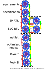
The original question was posed about verification in isolation, but it doesn’t work that way. Here is a simplified SoC design flow:

An SoC design stage depends on receiving quality deliverables from earlier stages – low quality deliverables will add debug time and additional releases. A basic part of the model will be the costs associated with making and receiving deliverables, and the costs of remedying low-quality deliverables.

For discussion, here is a further simplified version of an SoC design flow, showing only one IP being delivered into an integration.
Both of these diagrams are “manager diagrams”: they differ from reality in that all of the blocks appear equivalent, and all the arrows point in the same direction. In real life, the blocks represent stages with very different types and amounts of work, and there are loops in the flow.
A more detailed model
Almost every stage has some type of iterative activity: refining requirements, evaluating different architectures, getting RTL to compile, debugging errors, converging on timing closure, improving test coverage, etc. These iterative steps, deliverables, and feedback paths are represented in the next diagram.

By modeling both the iterative actions within stages and the interactions between stages, we are able to evaluate tradeoffs both within the stage and in the overall design flow.
While this model is applicable to the entire design flow, it does not have to be complete to be useful – a partial model using conservative estimates instead of measured data can still be very helpful. In the discussion below we will focus on RTL creation and verification activities.
Let’s look next at what is modeled within a stage.
Costs of preparing and accepting deliverables
In order to model the design flow, we need to account for the hand-off of deliverables from one stage to the next. Depending on the stages involved, the deliverables could be a written set of requirements, a C++ reference model, IP RTL, verification IP, netlists, etc.

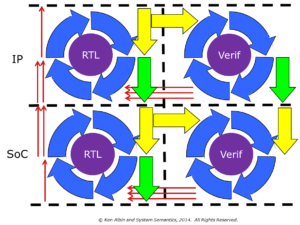
There is a cost incurred by a stage accepting a deliverable from a previous stage: unpacking, integration work, updating testbenches, regression testing, updating documentation, etc. This is represented by the yellow arrow in the diagram.
There is also a cost incurred by a stage when preparing to release a deliverable for a subsequent stage: more extensive testing, documentation, checklist reviews, tagging, packaging, etc. This is represented by the green arrow in the diagram.
In both cases, the cost could be large or small depending on the specifics of the deliverable and the amount of automation.
A stage can receive deliverables from multiple sources, but this is not shown in the diagram. In particular, project-level requirements and specifications need to be communicated throughout the design flow, and implementation details need to be passed on from prior stages.
The cost of a bug-free design
A thought experiment: if you were given a design that had no defects, what would you do to confirm it was correct?

You would probably create a normal verification plan and execute on it: building testbenches, creating tests, measuring coverage, holding code reviews, proving properties, etc. until the plan was complete.
For now, let’s assume the bug-free design is complemented by a bug-free verification environment that is constructed as part of your verification plan.
The activity needed to confirm a defect-free design defines the stage’s activity (and cost) baseline, shown in this diagram as the purple circle in the stage. This is work that always has to be done, and errors in the design or verification environment represent additional incremental costs that we would like to shrink to zero.
The incremental costs of bugs
A common idea in industry is the “debug loop,” shown in the diagram as the blue arrows.

We have divided the debug loop into four segments:
1) Detection (linting, random testing, code inspections, property proofs, etc.)
2) Isolation (manual debug effort)
3) Fix and Regression testing
4) fix Integration and Commit
Note that there are likely Fix/Regress or other iterations within the overall debug loop, but we won’t separate them out for this top-level model. Iterations within the debug loop would be a logical place to look for efficiency improvements by adding the next level of detail.
The ratio of resources used for Detection vs. Isolation will change over the course of the project: with an immature design it is easy to detect more bugs than engineers have time to isolate and fix; towards the end of the project much more resources are needed to detect bugs for engineers to isolate and fix.

Also, not all bugs use the entire debug cycle:
– A bug that was created in the current stage may be detected and isolated but not fixed due to resource constraints or other planned changes.
– A bug in a deliverable from a previous stage can be detected and at least partially isolated, but will generally be reported to the stage where it originated (shown as a red arrows in the diagram) where it will be fixed and included in a future release.
– A bug introduced in the current stage may go undetected until after it is delivered to a subsequent stage. While the downstream stage paid the price of detection, the current stage has to execute the rest of the debug loop steps and possibly initiate a delivery with the fix.
This model should account for nearly all of the activities performed in each stage. Next we model interaction with parallel stages.
Parallel stages
It is common for a stage to have parallel activities being performed by other teams: verification, emulation, power analysis, performance verification, etc. These parallel stages have their own stage model and are often tightly coupled to the primary stage. The hand-off cost could be as simple as tagging with a cron job, and the communication of bugs could be minimal through a shared issue tracking system.

In this diagram, both IP and integration stages have parallel verification stages. As part of the IP deliverables, verification IP is delivered from the IP verification stage to the integration verification stage.
Putting it all together
This cost model can account for all of the major costs involved in each stage of the SoC development process.
With the top-level model described above, we can create cost-to-fix charts accurate for the project, rather than the industry standard swag of 10X larger per stage.
The model requires some data that not every project tracks, but much of it is available (e.g., license usage logs of debug tools, regression resource usage identified by naming conventions, etc.) and percentage estimates of activities (e.g., 10% of bugs come from prior stages) are enough to get started. Values estimated now can be collected directly later, and areas needing closer scrutiny (e.g., fix/regress loops in the debug cycle) can be modeled in more detail.
The next post will discuss application and implementation of the cost model in more detail.
© Ken Albin and System Semantics, 2014. All Rights Reserved.